We are planning on using the standard Voltera boards, namely the 2x3, with our desktop pick&place.
I’m using Eagle / Fusion and have located the Voltera-provided board template component in my PCB layout at 0,0. I am planning on using the two locator dots on the lower left and upper right corner as registration marks so that I can get discrete alignment of the circuit on the template board. Then, I’ll use the registration marks to align the P&P and voila (hopefully), automatically placed components!
I didn’t see any articles on this in the forums or help files, so I thought I’d share my experience and ask if anyone has come up with a more efficient solution.
-
Download the component library and place the 2x3 template (I used v2) at 0,0
-
Output the board using the Voltera cam job as normal
-
Jump into the Print/Solder/Drill workflow as an Aligned job
-
The two registration dots show up as drill holes - use both to align circuit
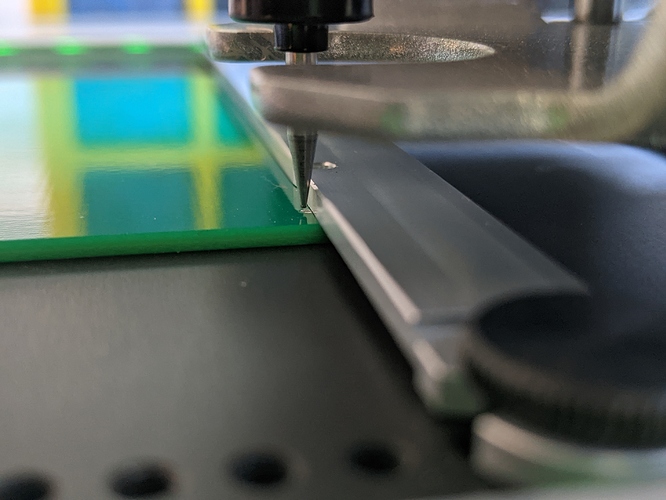
I aligned the bottom left hole to be adjacent to the left notch in the clamp bar for added clearance. The problem is that the upper right hole is really close (partly obstructed) by the board clamp - since the right notch doesn’t line up with the registration dot. The probe clears the bar, but only barely, and leaves me a bit nervous that a slight misalignment will send the probe crashing into the clamp bar.
Aside from intentionally angling the clamp bar for some more clearance or machining a notch into the lip, has anyone found a better way?
