Hey guys,
Thanks for the feedback, it’s super valuable to us as we continue to try and improve the V-One and it’s software.
You should be able to select features for drilling. Once you’re actually at the point where you’re drilling you can select any of your holes in the same way you can select any tool paths and print them individually in the print step.
There isn’t really anything we can do about the power button, that’s one is hardware level and would require quite a bit in order change it to what you propose.
I’m curious the application for increasing the timeout on holding the motors. This hasn’t come up before. Currently you can do it on a per session basis if you wanted using the M18 command, I’ll go into that a bit later.
I’m not sure I totally understand what you mean by “bypass wizard steps”. As far as having to re-align the board that will happen if your circuits bounding box changes at all. You can mitigate this by creating fiducials that exist beyond the normal bounds of your circuit to generate a larger bounding box when loaded, then as long as any changes you make to the circuit are kept within that area you should be fine.
When it comes to probing there really isn’t a lot to be done there. Based on the delicate nature of height mapping it’s super risky to reuse probing targets. The software has no way of knowing the if the state of the board has changed. Coupled with the fact that even seemingly minor changes may require new probe points to properly map the board the best bet is to simply reprobe the circuit.
We’ve had a few users ask about changing the location of the calibration pattern. It’s something I’d like to do once we’ve got time for it as it would be especially useful for those who have special coatings on their substrates or those with boards smaller than the pattern. Those are fairly rare cases but definitely something I’d like to better accommodate.
Keep out zones is another thing we’re definitely aware of and I think it would be a great thing to implement. This has mostly been talked about in the context of printing on a board that may have existing features. In the interim we’ve added the tool movement travel height to the beta settings tab which can help with that.
I’m not sure what more could do without the printer attached. At this point you only get stuck after the printer would need to do something. Do you have an example of where this would be useful to you or what you’d like to do beyond loading and positioning a circuit?
There isn’t really a solid way for us to do manual dispensing, that’s definitely a little heavier than it sounds. In terms of drilling I imagine that would be doable although perhaps a bit risky. Ideally all the holes you need would be in your drill file.
I like the vacuum attachment you’ve put together. I’d definitely be interested to see the results you get with it. If you were able to get a video that would be rad. It’s something that hasn’t seemed super necessary given how little material comes off the boards during normal drilling. Here at the office I’ll hit it with a vacuum after drilling to maintain my alignment which works well.
In terms of tweaking alignment ideally a re-align is your best best if you check during the alignment verification step and find you’re not hitting where you expect. That said we do have a console which will give you more flexibility in terms of tweaking things. You can open up the console with ~ or ALT+C. From there you’ll want to first use the M18 to adjust your motor timeout. I’d recommend M18S300 which will change the default timeout from 2 minutes to 5 minutes. The value after S is in seconds so adjust for as much time as you think you need.
Next the command G92 will set your current coordinates of the tool. So after you either print something to test your alignment or use the probe to verify alignment you can do something like G92X-0.1;V1X0Y0. After printing the tool will always return to X0Y0 so the previous command will tell the printer that the tool is actually at negative 100 microns then the V1 command will move the tool to the new X0Y0. The important thing to remember is that you want to move in the opposite direction that you want the tool to move.
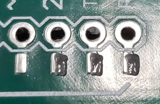
So here’s an example

you can see I’m too far to the right. So I used the above command G92X-0.1;V1X0Y0 and tried again.

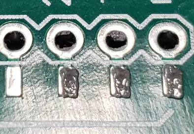
You can see it’s a little bit better but still not where I want it. So I ran the same command again.

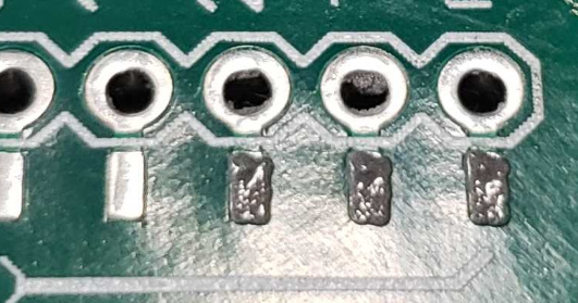
Now it looks great. It does look like it’s a little low as well but this was just a proof of concept. You can of course do the same thing with G92Y-0.1;V1X0Y0 to adjust the Y position.
Of course if I was too far to the left I’d be doing G92X0.1;V1X0Y0 instead of the negative value. It’s also important to remember that you’re setting new 0,0 coordinates so the next time you run the command it will be a relative step. 0.1 should be a solid value for moves but you can of course adjust as needed. Just remember that if you already did 0.1 then of course doing 0.2 will put you at 0.3 from the original position.