I originally bought the V-one for making convenient breakout boards, but it got me thinking about printing RF filters, antennas and such. With the high resistivity of the traces, and the fact they are not really solid I really wanted to try it out. I have to admit I'm actually pretty pleased with how well it went.
This is just an initial test, and I do plan on doing more.. so my first test setup is using some cheap MG Chemicals single side clad 1/16" 'PC Board' - I'm honestly not sure if its even FR4, if it is, its very poor quality, but it is the right thickness and seems to be a pretty consistent thickness. To further mess with the results, I printed this on the previous version of the software (days before the current version was released) which printed 3-4 layers of ink on some of my pads where the tracks came in.
Due to the lab I'm in, using hazmat chemicals in tanks and such isn't really an option (too much paperwork to get them in) so I'm not going to offer a comparison to an etched double sided board (ground plane + microstrip). Plus this test is in my own time, and I'm not a fan of etching boards - that's what we have China for.
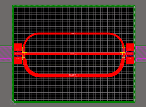
Test board in Altium:

- Top trace, "thin trace", is 1mm wide. 61.997mm long
- Centre trace is 1.384mm which Altium calculated to be 49.99ohms. 49.75mm long
- Bottom trace, "thick trace", is 2mm wide, 60.997mm long
I'm bridging the tracks to the SMA connector with the included Kester silver solder rather than using 0 ohm 0603 resistors as designed, mostly because I dont have any, and bridging the gap is pretty easy anyway.
I need to break this up as I'm a new user and can only post one image per post.... to be continued.