12 / 13
Aug 2021

So I started doing some tests - left things for a couple of hours, now i can't seem to get a good consistent calibration print. I have bump of the amount to plus 6 and still getting gaps./

Edit: I just tried again after bumping it to +10 and it start out okay but but the end of the print it really looking sketchy

Edit: Dialing it back to zero and nada comes out

Edit: okay i took off the dispenser and re-primed it and things are looking better

Edit: Still finding the longer it prints the worse it becomes.

Edit: Okay this is a new one. It only printing out calibration lines and no squiggles

Edit last pass it only printed out two lines..

Package sent

  • created

    Sep '16
  • last reply

    Aug '21
  • 12

    replies

  • 4.3k

    views

  • 4

    users

  • 2

    likes

  • 7

    links

I change nozzles when that happens. Grab a fresh nozzle and away you go - the old one i put back in the centrifuge vial and fill the vial 80% full with heavy duty flux remover, let it soak for a day shaking it every few hours. Then throw it in an ultrasonic cleaner for luck. Good to go again :smiley:

So with that weirdness happening I decided to close down the app and start from scratch. This time I got the print I was expecting

41

That looks an awful lot like a 2.4GHz stripline antenna.. did you modify the reference design for the resistivity of the ink?

With the ground leg, you really want to drill that to a low impedance ground plane (even if it's just wide copper tape) or your whole net of ground wires is going to mess with your tuning pretty impressively. You need a big low impedance path to ground :slight_smile:

This is just primarily a printing exercise. If I can get a working design then that's a bonus but I am not counting on it as at the end of the day, I will be using pre-certified modules.

But I am open to any suggestions to give it the best chance of succeeding.

I know squat about RF

Is that a 4 layer board, or is it a 1.6mm thick board with a ground plane on the bottom - my concern is how small your feedline is... if it's only a 2 layer board with 1.6mm of er4.2 FR4 between your ink and your groundplane, you need a track that is 3.12mm wide for your feedline (if it was copper). That track thickness looks more appropriate for a 4 layer board with a groundplane 0.2mm below the top layer. If your wire is too thin, your impedance match will be WAY off and you'll lose all your energy before you get to the antenna :frowning:

Umm 3.12mm? Are you sure about that? This is the same antenna setup used by the esp8266 for example. I do agree the antenna feed trace is way too thin.

https://www.eeweb.com/toolbox/microstrip-impedance2

Feel free to calculate it out yourself, I just used Altium to tell me. You'll note that an ESP8266 has a very thin PCB, my RF tests with the V-One were using 0.8mm FR4 because 1.6 was going to be way too big for track width. If you want to use 1.6mm FR4 for mechanical reasons, you go 4 layer and have your ground plane under 0.2mm of prepreg so your track width can be nice and small - allowing you to get it into SOC/RF chip pins easily :wink:

Curious to see how ink goes in a simulation, i've posted my results before from real world prints, but here's some simulations for you.

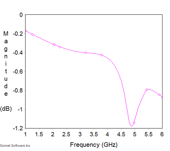
3.2mm wide trace, 40mm long, of V1 ink (0.012ohm/sq, 0.1mm thick) on 1.6mm FR4 with a lossless ground plane.

This is better than my real world testing came up with... but whatever, it gives us a relative point to work from. If this was copper, it would be an almost 50ohm trace - I'm using 3.2mm because thats the closest a V1 can print with it's 0.4mm printing width.

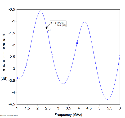
As a comparison, a 0.4mm wide, 40mm long ink track, on the same 1.6mm FR4:

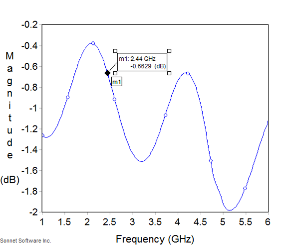
Even a 1.2mm wide ink track is far superior:

I don't have any single clad FR4 that is 1.6mm (1/16") thick around, or I'd print you some tracks to show you real world results :frowning:

I tried simulating your antenna in Sonnet Lite, but it's not software I'm used to so I dont seem to be getting much out. My employer sadly doesn't have any EM simulation software so sadly i'm stuck with the free version of Sonnet for simulation. I've sent them a request to find out what the educational pricing would be (I work in applied research at an academic institution) - could be interesting to see.

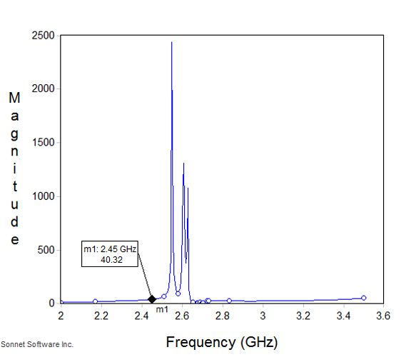
As an example, here's a straight 30.6mm microstrip stub that should just be a 1/4 wave antenna... 100mm of air on all sides except the base which has the ground plane... i'd expect he VSWR of this to be basically 1, and S11 to be SUPER low... but VSWR is 40.32:1, which would mean as an antenna this is losing more than 95% of signal. So clearly, I have something in their software setup wrong! Easy enough to simulate filters and other 2 port elements... but I've not tried single port features in here before.

4 years later

Hello,

I am wondering if you are aware whether the conductive material will be suitable for printing millimeter-wave antennas operating at 60 GHz or 77 GHz?

Thanks.

Thanks, @pion. I think the high thickness and roughness of the material could limit the conductivity to lower frequency. Any thoughts on printing passive antennas, like reflective tags, with this?

Also, I wonder if it is feasible to use Copper ink (like https://www.copprint.com/3) with V-One. Voltera says that we can use Copper ink too, but not sure if they can handle it. I couldn’t find any examples.